Basic Circuit Simulations
I've recently started working on a research project for university, and as a part of that am doing some more circuit simulation work. So, in an effort to tackle more of the #HamChallenge, I wanted to showcase how I do simulations for Week 22.
Week 22: Simulate an electric circuit! Use a circuit simulator to simulate any electric circuit! If you have never simulated a circuit before, you may find on-line simulators like CircuitLab a great starting point.
The HamChallenge.org recommends a few different designs: rectifiers, inverters, amplifiers, and filters. Today, I am going to showcase two different recommended designs in two different simulation software programs.
The Full-Wave Rectifier
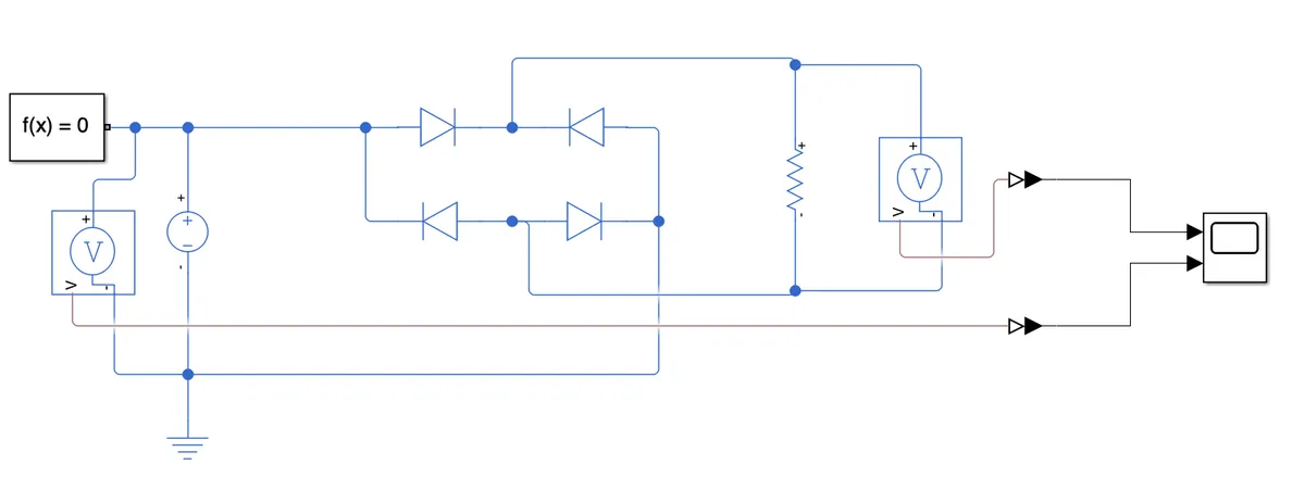
The full-wave rectifier takes an AC input, and flips the negative side to positive - creating a rising and falling DC source.
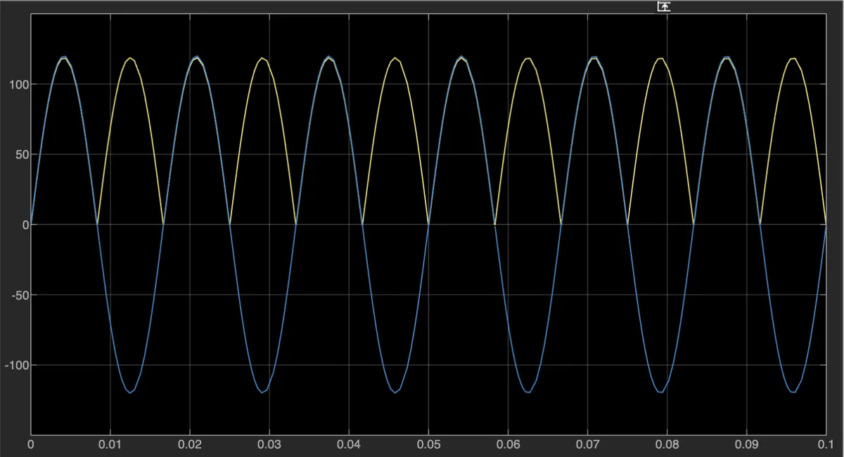
In the image above, you can see the output of the simulation. The blue line represents the input AC voltage - in this case I chose to use a 120V 60Hz source similar to what you'd see in a home electrical system. The rectifier works as expected!
I chose to do this simulation in MATLAB's Simulink software platform. In my opinion, this is not ideal for hobby users who just want to simulate for amateur radio projects, but this is the main platform I've been taught to use throughout my time as an electrical engineering student. It has a decent library of parts, with enough flexibility to create parts that don't yet exist, and capabilities for Arduino visual programming and other neat features!
My main problem with Simulink is that is has lacking support for AC Analysis - it is possible but requires some higher level knowledge of how to do MATLAB code with Simulink models. I've done it once for a class, but I find it a bit too complex for my taste. I expect I'll become more familiar with it over the coming months as I do more projects, but for AC Analysis there are other programs I much prefer.
~7 MHz Low Pass Filter
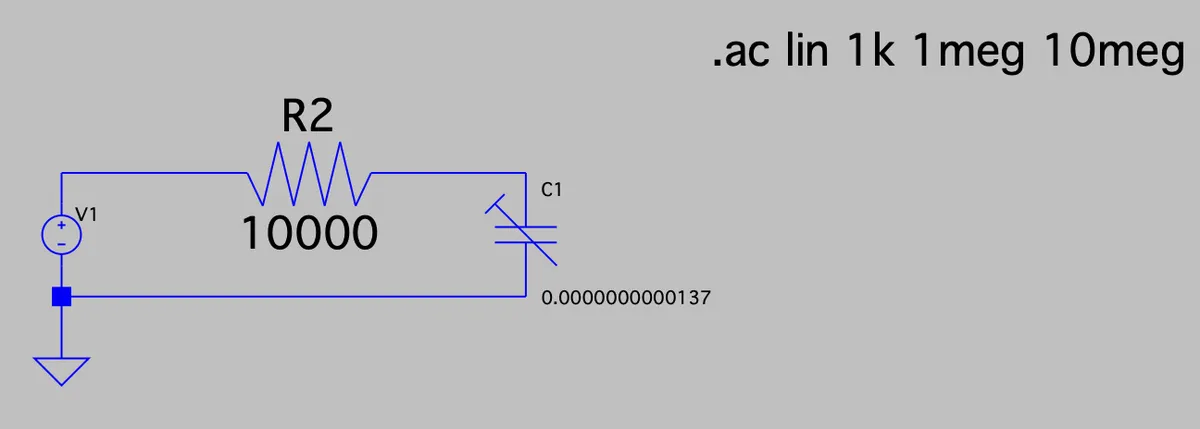
A low-pass filter is used to reduce the amplitude of frequencies higher than a specified point.
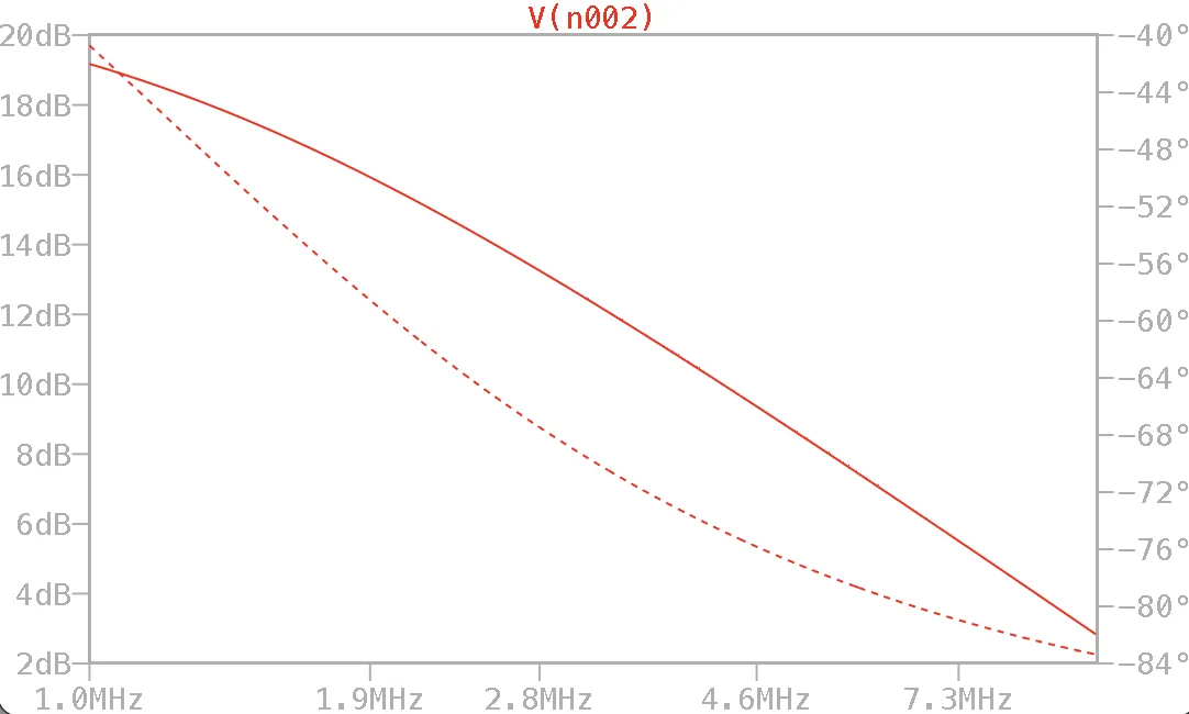
As you can see, I didn't exactly hit the mark on the cutoff frequency as I had hoped, but I didn't do as bad as I expected! This design was found in David B. Rutledge's "Electronics of Radio" textbook, and I calculated a 10k ohm resistor and a 0.137pF capacitor for a cutoff frequency of ~7.3MHz, although it seems this design might need some finer tuning.
I had to learn LTSpice for a lab class this past semester, and have really enjoyed using it since! While the support on Mac isn't the best, the program is highly flexible, widely supported by user-created components found across the web, and fairly easy to pick up with the help of some StackExchange posts and documentation. This is now my go-to for AC Analysis, as it is built for that functionality much more than MATLAB is!
I do hope to get a Windows machine soon, in part to have a much easier time using this software with a better interface, but I highly recommend LTSpice for any hams looking for a free program to get into circuit simulations.
Conclusion
I'd love to know what other hams are doing for their simulation work, especially tools that are more focused towards RF. Let me know by sending me an email to cj (at) my callsign (dot) radio, or by reaching out to me on the Fediverse (@roguefoam@polymaths.social).
I hope this post was at least somewhat informative to a few people out there interested in circuit simulation. I am nowhere near an expert, but thought I'd share what I'm working on anyways while I am learning more about simulations every day!
73, WW0CJ